Panoramas and trajectories are examples of feature layers. These layers contains geometry (points, lines, polygons) and associated attributes (numbers, file names, text, etc.) defined by a category.
Collage Web supports the creation of custom feature data. Users can define their own categories with a custom attribute list, and use them to create layers where extracted features are stored. These layers can be exported to files in standard formats.
Categories are lists of attributes, sometimes called "fields" or "columns". These named lists are used to initialize the attributes of new feature layers. For instance, a category named "Buildings" is a list with the attributes that an organization typically uses to create feature layers that represent buildings. It may include fields like Height, Use type, Owner, Cadastral ID, etc.
Categories are templates which help to create new feature layers. However, if a category is modified or removed, it will not affect any layers previously created from it, only the new layers.
As with projects and layers, a user needs proper permissions to create, modify or delete categories. Also, as the other objects managed by Collage Web, categories are only visible inside an organization. They cannot be shared among different organizations.
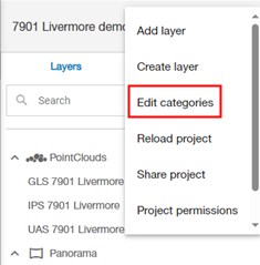
To open the Category Manager, use the "Edit categories" menu option in the Layer Manager. This dialog should be used by the organization data manager to define the types of features to be used in the organization, so different users can create and extract features with consistent attributes (e.g. all extracted buildings have the same data fields).
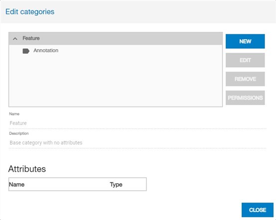
The Category Manager shows the tree (hierarchy) of categories. Each category inherits all the attributes from its parents.
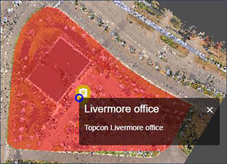
By default, there is a root Feature category (with no attributes), and a child Annotation category with a name and a description. All categories descending from Annotation will include these attributes, which will be displayed in a popup frame by the Information tool. If a user does not want this popup to show, he/she can create categories which inherit directly from Feature.
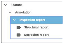
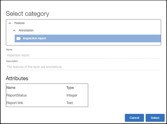
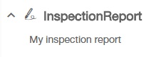
In this example, an InspectionReport category has been created as a child of Annotation. Therefore, it will inherit the name and description attributes, plus it can have additional fields. Two child categories (StructuralReport and CorrosionReport) have been created to add more attributes to the basic InspectionReport.
To create a new category, select the parent one in the tree and click on the "New" button. The new category will be automatically set to Edit mode. Its name, description and attributes can be modified.
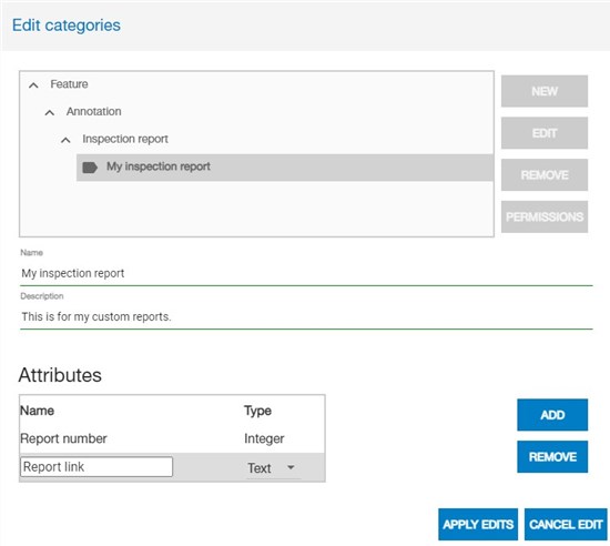
To save new category data, click on "Apply edit". Otherwise click "Cancel edit" to revert the changes.
To edit an existing category, select it in the tree and click on the "Edit" button.
Categories without children can be deleted by clicking on the "Remove" button.
Annotations are a quick way to add new data to the project, for inspection and inventory applications. As other feature data, annotations will have an associated Category with the fields or attributes the user needs to include with each element, so it is a good idea to create the required categories in advance.
To add or modify annotations, activate the Annotation tool:
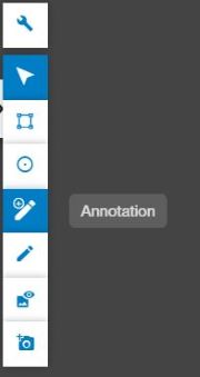
If the project does not contain yet a layer to store the annotations of the selected geometry type (the default is Point), the application will prompt the user to create the layer.
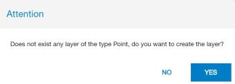
See the section create feature layers below for details on this dialog.
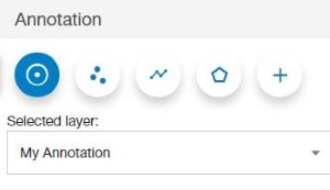
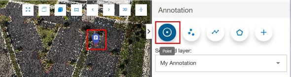
The Annotation tool panel allows the user to change the type of geometry to create when annotating (point, multipoint, polyline or polygon). In each case, a layer of the proper type will be selected (the user can also select it manually). If there is not layer of the selected type, the user will be prompted to create one.
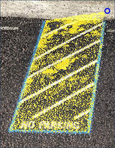
To create an annotation element, the user will click on the 3D view to draw the element (point, multipoint, polyline or polygon). Double-click must be used to finish the drawing of a geometry other than a single point.
When the drawing is finished, the user will be prompted to fill in the fields (defined by the layer category) of the new annotation element:
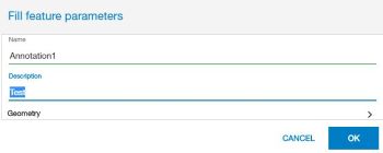
If necessary, the user can modify later the annotation by clicking on it and changing the field values in the properties panel.
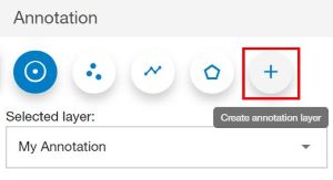
At any time, the user can create a new annotation layer by clicking on the "Create annotation layer" button in the tool panel:
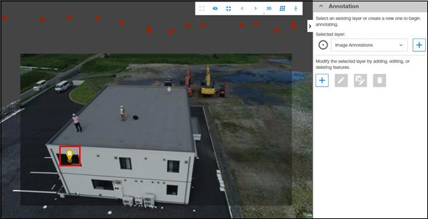
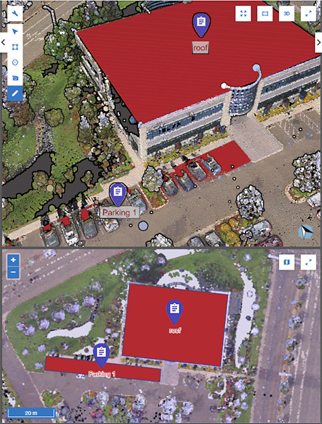
In image mode, it is also possible to add annotations, which is especially useful when the project includes results from an aerial survey. These annotations are directly linked to the image where they were added, making it easy to inspect and quickly add relevant observations.
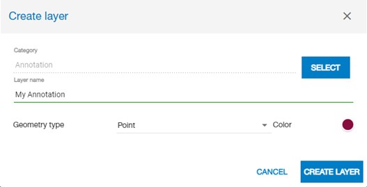
To create a new feature layer, select the "Create layer" menu option in the Layer Manager.
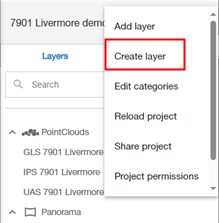
The Create Layer dialog will appear with empty data.
Click on the "Select" button next to the category field to open the Category Selector. Choose the category for the new layer in the tree and click "Select".
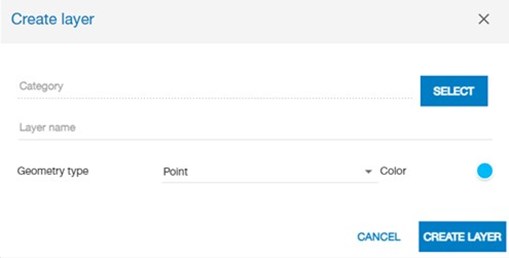
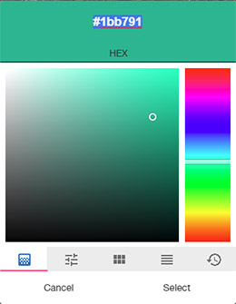
The name of the selected category will now appear in the Create Layer dialog. The user must now type a layer name and select its geometry type and color.
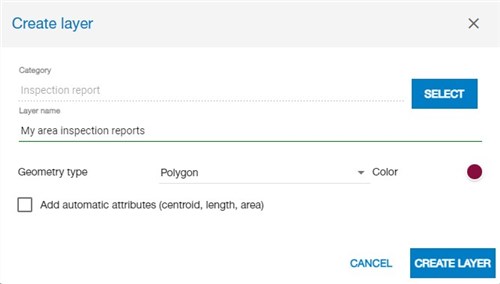
For multipoints, lines and polygons, the user can select the option to have automatic attributes calculated. These attributes (centroid, length/perimeter and area) depend on the geometry type and will be automatically calculated.
The new layer will appear in the layer manager under a group with the category name.
Because this layer is empty (it contains no features), nothing is visible yet in the view. Now, the user can add features to the layer.
While the annotation tool is a convenient way to quickly add vector elements, the user might need to perform other operations like modifying the elements' geometries or deleting them. The Editing tool operates on Annotation layers as well, so both tools can be combined.
To add or modify features in a vector layer, activate the Layer Editing tool:
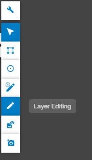
Then, select in the Layer Manager the feature layer to extend or modify.
Once the Layer Editing tool is active and a feature layer is selected in the Layer Manager, the Tool panel on the right side will show the editing operations available to the user.
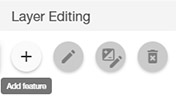
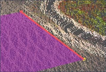
After selecting the "Add feature" operation, the user can extract a new feature by picking points (from point clouds) in the 3D View. Depending on the geometry type of the selected feature layer, it will be possible to draw a point, multiple points, a polyline or a polygon.
For polyline or polygons, the user can add as many points as needed and then:
See notes about picking in the Measurement section.
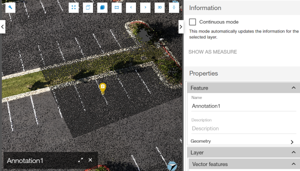
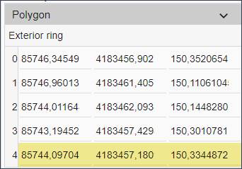
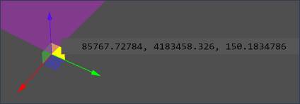
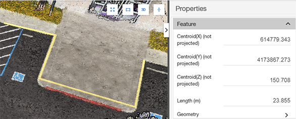
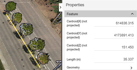
The captured coordinates can be displayed in the Properties panel by expanding the "Geometry" group. These coordinates will be shown here in the Projects' coordinate reference system:
The user can also type the attribute values for the new feature in the Properties/Feature panel. Text must be entered for a "name" attribute, if present.
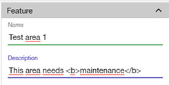
Note that it is not necessary to use the Edit tool to change the attribute values in the Properties panel. It is enough to select the feature with the Information/Selection tool.
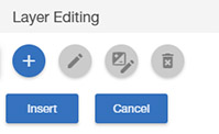
To save the new feature, click on the "Insert" button.
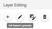
When a feature is selected, the Layer Editing panel offers additional tools to modify its geometry:
Edit feature vertices
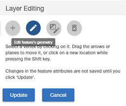
In this mode, a feature vertex is selected, either by clicking on it in the 3D View, or in the Geometry list inside the Properties panel.
The selected vertex is decorated with three axes and planes. The user can use one of the axes or planes to click and drag the vertex to change its location (the active axis or plane will be highlighted).
Alternatively, the user can move the vertex to a point picked from a point cloud by holding SHIFT and clicking on the destination point.
Add or remove vertices
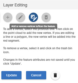
In this mode, new vertices can be added or removed. For lines and polygons, a vertex is selected, either by clicking on it in the 3D View or in the Geometry list in the Properties panel. The next feature segment will also be selected (highlighted in red).
When the user clicks on the point cloud, an intermediate vertex will be added to the feature in the middle of the highlighted segment.
To remove the selected vertex, just click on the trash bin icon next to the cancel button.
Remove the feature
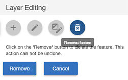
This operation is used to remove the whole feature. The user needs to confirm by clicking on the "Remove" button.
Notice that, currently, Collage Web does not support Undo/Redo operations, so some updates are not reversible. The user will see a warning when this is the case.
Create feature from a measurement
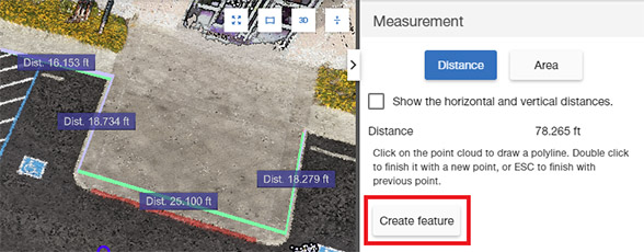
If a distance or area measurement has been defined, it is possible to save the geometry (together with the distance or area value) as a vector feature in an existing layer.
To do so, select a compatible vector layer (lines for distance measurement, polygons for area measurement) and click on the "Create feature" button in the tool panel.
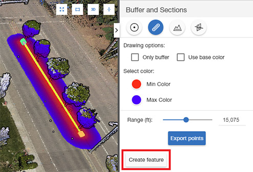
Create feature from a buffer or section
If a point or line has been defined to create a buffer or section, it is also possible to save this geometry (together with the length, in the case of a line) as a vector feature in an existing layer.
To do so, select a compatible vector layer (containing points for a point buffer, or lines otherwise) and click on the "Create feature" button in the tool panel.
The user can find the vector layer style options in the Properties panel.
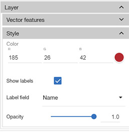
All feature layers have these style options:
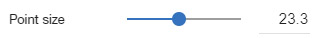
In addition, point vector layers have a Point Size property.
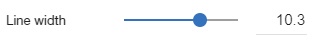
And line vector layers have an additional Line Width property.
This advanced symbolization technique allows users to apply different symbols to the features of a vector layer depending on the values of their attributes. For instance, if our vector layer has an attribute specifying the status of each object, we may want to use different colors depending on the value of this status field.
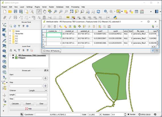
To see the attributes and values of a vector feature layer, we can use the table view.
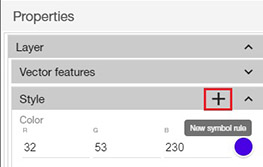
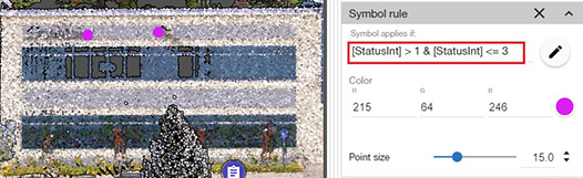
The first step is to add a new symbol rule in the layer style properties:
By default, the condition of this symbol rule is "true", so it will be applied to all features.
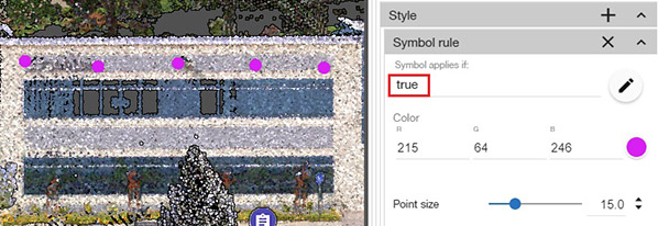
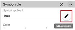
We can change the condition to use an expression based on the feature attributes. To modify this expression, type on it or click on the "Edit expression" button:
In the Expression Editor, the user can select an attribute and an operator to compare with a typed value. Two comparisons can be combined by using the "And" option.
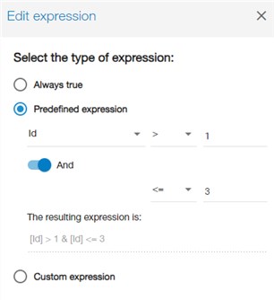
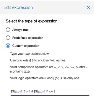
Alternatively, we can directly type the expression.
Note that features will be invisible (transparent) when no rules apply to them.
By adding more rules with different conditions, we can apply different drawing options to the features depending on their attributes:
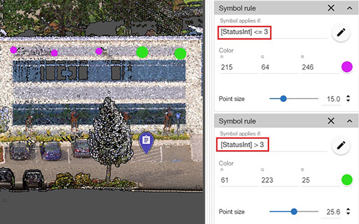
Note that rules are applied from top to bottom. If a rule applies to a feature, the lower rules are not considered.
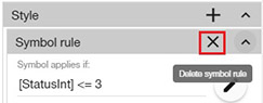
The user can also remove a rule by clicking on its 'X' icon.
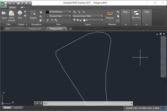
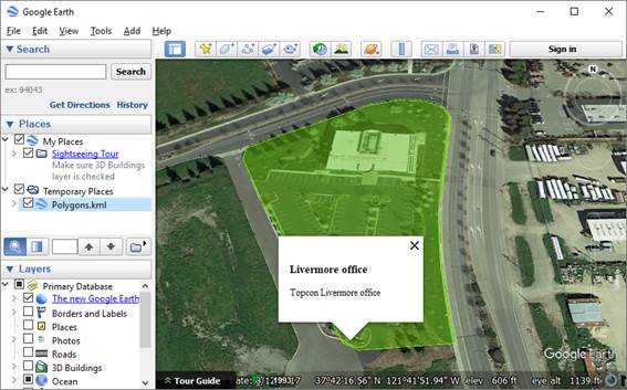
After a feature layer is created, the geometry and attributes are stored in the Collage Web cloud database. The layer features can be exported to a file in the local computer, to be used in CAD, GIS and other software packages.
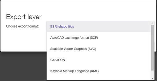
To export a feature layer, use the "Export layer" menu command.
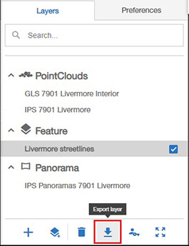
In the Export Layer dialog, the export format can be chosen: